


Margaret Edney d3.0.2 01/04/03
This example describes a test of the procedure used for handling personnel transfers in a large organization. The purpose of the testing is to verify valid routes through the system, ensure that there are checks in place to identify lost cases and confirm that there are no invalid routes through the system.
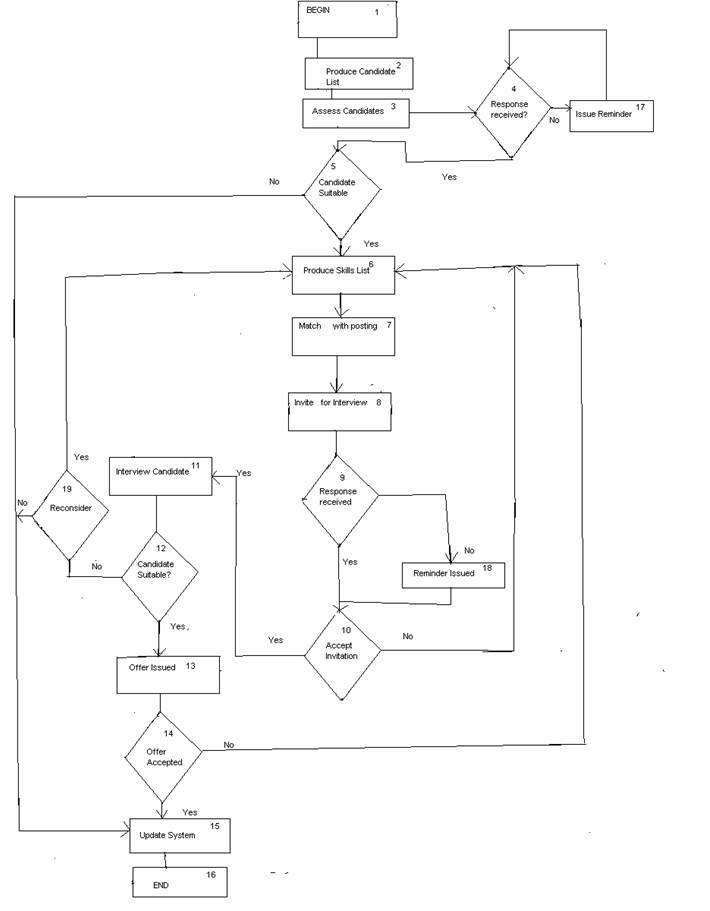
All personnel eligible for transfer were identified on a system produced candidate list. This was reviewed manually and potential candidates were identified. Skill lists showing potential candidates were produced, by the system, and manually considered against available postings. Three weeks were allowed for this process. Reminders were sent out after 2 weeks. Candidates matching individual postings were input to the system, which then produced interview invitations. Candidates could reject the interview and be considered for other postings. Candidates were allowed 2 weeks to respond before a reminder was issued. If there was no response within a further week, the candidate was assumed to have rejected the interview and was reconsidered for other postings. Following the interview, results were input to the system. Results were “success”, “reconsider” or “reject”. Successful candidates were notified. Candidates labeled “reconsider” were eligible for other postings. Candidates labeled “reject” were no longer considered during this round of selection. All unsuccessful candidates, whether for reconsideration or rejection, were notified.
The system as initially specified did not place any limits on the number of times a candidate could reject, or ignore, an interview invitation. This was later changed to a maximum of 3 invitations. The candidate then had to wait for the next selection round.
A major consideration in Procedure Testing is identifying areas where cases can be lost (“black holes”) or delayed by users. Test cases were designed to exercise the steps of the procedure with emphasis placed on ensuring that all inputs and outputs are reconciled.
Inspections and reviews (Software Inspection: Gilb, T. and Graham, D., Addison Wesley, 1993) of the procedure requirements were used to identify all transitions and any possible “black holes” or “pending trays”.
Flowcharting techniques were used to describe the procedure flow.
All branches was chosen as suitable coverage criteria.
The different paths through the process were identified from the flowchart.
The Inputs to the system are:
|
Input |
|
Possible Inputs |
|
A |
Candidate suitability |
Y / N |
|
B |
Response from consideration received |
Y /N |
|
C |
Candidate matched with posting |
Y / N |
|
D |
Candidate response received |
Y / N |
|
E |
Candidate response to invitation |
Y / N |
|
F |
Interview result |
Y / N |
|
G |
Reconsider for other postings |
Y / N |
|
H |
Acceptance of offer |
Y / N |
To achieve branch coverage, the paths through the process are:
|
Path |
Steps |
Result |
|
1 |
4 ® 5 ® 6 ® 9 ® 10 ® 11 ® 12 ® 13 ® 14 ® 15 |
Accepted Offer |
|
2 |
4 ® 5 ® 6 ® 9 ® 18 ® 10 ® 11 ® 12 ® 13 ® 14 ® 15 |
Accepted Offer Interview reminder |
|
3 |
4 ® 17 ® 4 ® 5 ® 6 ® 9 ® 10 ® 11 ® 12 ® 13 ® 14 ® 15 |
Accepted Offer Consideration Reminder |
|
4 |
4 ® 5 ® 6 ® 9 ® 10 ® 6 |
Interview Declined |
|
5 |
4 ® 5 ® 6 ® 9 ® 10 ® 11 ® 12 ® 19 ® 6 |
Candidate for Reconsideration |
|
6 |
4 ® 5 ® 6 ® 9 ® 10 ® 11 ® 12 ® 19 ® 15 |
Candidate Rejected |
|
7 |
4 ® 5 ® 6 ® 9 ® 10 ® 11 ® 12 ® 13 ® 14 ® 6 |
Offer Rejected |
|
8 |
4 ® 5 ® 15 |
Candidate not Considered |
This exercised each transition between automated and manual states. Sequences of transitions were also used.
Chow’s coverage measures were used. “0-switch” which covers each transition, was used as a minimum, giving 100% transition coverage. In addition, “n-switch” to cover possible n+1 long sequences of transitions was used to detect possible transition errors, missing or extra states.
Each transition is between the automated state and the manual state.
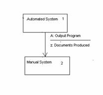
Or between the manual state and the automated state.
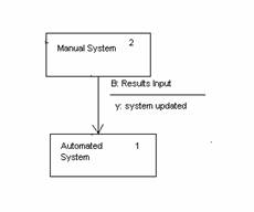
|
State |
Condition |
|
|
A |
B |
|
|
1 |
2 / z |
1 / N |
|
2 |
2 / N |
1 / y |
Each stage in the process can be considered as a sequence of transitions between a “waiting” state, a “listed” state and a “decided” state as shown in the diagram:
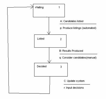
From the state transition diagram, a state transition table was produced.
State |
Condition |
||
|
A |
B |
C |
|
|
1 |
2 / p |
1 / N |
1 / N |
|
2 |
2 / N |
3 / q |
2 / N |
|
3 |
3 / N |
3 / N |
1 / r |
A full state transition diagram for the system shows each step in the process and the input that triggers each transition.
Use case modeling can be used to identify use cases.
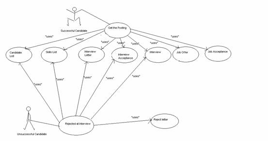
This diagram is very simplified. Additional use case models would include candidates who failed to respond to invitations or who refused the interview, candidates who were rejected at the beginning of the process and candidates who were to be reconsidered for other postings.
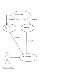
An additional Use Case is the Placement officer as shown in the following diagram:
The partitions include:
| Successful candidates | |
| Candidates who do not respond to invitations | |
| Candidates who are rejected but reconsidered | |
| Candidates who are rejected following interview | |
| Candidates who are not considered for transfer | |
| Candidates who refuse offers | |
| Candidates where there is no response from Placement officer. |
|
Case |
Input |
Path |
Expected Outcome |
|||||||
|
A |
B |
C |
D |
E |
F |
G |
H |
|||
|
1 |
Y |
Y |
Y |
Y |
Y |
Y |
- |
Y |
1 |
Candidate Accepted. System Updated |
|
2 |
Y |
N |
Y |
N |
Y |
Y |
- |
Y |
2, 3 |
Candidate Accepted System Updated |
|
3 |
Y |
Y |
Y |
Y |
N |
- |
- |
- |
4 |
Candidate on new List |
|
4 |
Y |
Y |
Y |
Y |
Y |
N |
Y |
- |
5 |
Candidate on new list |
|
5 |
Y |
Y |
Y |
Y |
Y |
N |
N |
- |
6 |
Candidate rejected |
|
6 |
Y |
Y |
Y |
Y |
Y |
Y |
- |
N |
7 |
Candidate on new List |
|
7 |
Y |
Y |
N |
- |
- |
- |
- |
- |
8 |
Candidate rejected |
Case 1 – A candidate selected for interview; all responses received on time; candidate accepts offer.
Case 2 – A candidate selected for interview, both responses require reminders, candidate accepts offer.
Case 3 – Candidate rejects interview. Candidate on new list
Case 4 – Candidate marked for reconsideration following interview. Candidate on new list
Case 5 – Candidate rejected at interview.
Case 6 – Candidate rejects offer. Candidate on new list.
Case 7 – Candidate rejected at consideration stage.
Test cases were selected to cover each single transition, for example receipt of candidate selections:
|
Chows 0 Switch Coverage |
|||
|
Test Case |
Input |
Transition |
Expected Outcome |
|
1 |
Candidate selected |
2 ® 1 |
System updated |
|
2 |
Candidate rejected |
2 ® 1 |
System updated |
|
3 |
No response |
- |
System unchanged |
In practice, many cases would be required to cover all transitions identified.
Case 1 – A successful candidate
Case 2 – A candidate where responses are not received
Case 3 – A candidate who rejects the interview
Case 4 – A candidate who rejects the offer
Case 5 – A candidate rejected at interview
Case 6 – A candidate who rejects the offer
Case 7 – A candidate who is rejected at the consideration stage.
Case 8 – A Placement officer who fails to return their selection lists.
|
Case |
Input |
Input Partition |
Output Partition |
|||||||
|
A |
B |
C |
D |
E |
F |
G |
H |
|||
|
1 |
Y |
Y |
Y |
Y |
Y |
Y |
- |
Y |
All acceptances. All responses in time. |
Successful candidate |
|
2 |
Y |
N |
Y |
N |
Y |
Y |
- |
N |
Delayed responses. Rejected offer |
Candidate on new list |
|
3 |
Y |
Y |
Y |
Y |
N |
- |
- |
- |
Candidate rejects interview |
Candidate on new List |
|
4 |
Y |
Y |
Y |
Y |
Y |
N |
Y |
- |
Candidate for reconsideration |
Candidate on new list |
|
5 |
Y |
Y |
Y |
Y |
Y |
N |
N |
- |
Candidate not for reconsideration |
Candidate rejected |
|
6 |
Y |
Y |
N |
- |
- |
- |
- |
- |
Candidate not considered |
Candidate rejected |
Case 1 – A successful candidate
Case 2 – A candidate where responses are not received in time and rejects offer.
Case 3 - A candidate who rejects the interview
Case 4 – A candidate who rejects the offer
Case 5 – A candidate rejected at interview
Case 6 – A candidate who is rejected at the consideration stage.
5. Implementation of Test Cases
The test cases would need to be implemented in a database. A database of skills would also be required.
Each transition between the automated and manual system was checked.
Data Preparation tools could be used to prepare the test database.
Because Procedure testing exercises the interactions between the computer system and the manual systems, automation of the actual testing is limited.
Procedure Testing involves the consideration of the process as a whole, to ensure that the flow through the system is complete. It also considers each separate interaction between the user and the system to ensure that all are complete. It looks particularly at areas where there may be an expected input or output that does not occur.
Procedure testing does not verify the functionality of individual components of the system, nor does it consider performance aspects. These would be covered by other areas of testing.
Please send any comments you have on the example using the Feedback Form.
| Comments from Marco Giromini | Comments on
non-functional Testing Examples:
Procedure - MIS. “Requirements/Specification …” – “Reminders were sent out after 2 weeks.” I suggest to add “If there was no response within a further week, the candidate was assumed to have rejected the consideration invitation” I also suggest to change “success” with “suitable”, to avoid confusion with “Successful candidates”. “Analysis of Requirements” – “flowchart” “Match with posting” should be a condition, with two outcomes: Yes and No (see “Test Design” - “Equivalence partitioning” – “Test case 6”. I suggest to mark each condition in the flowchart with the corresponding Input, reported in the 1st table of “3. Test Design”). I.e. marking 4 with B, 5 with A, 7 with C, 9 with D, 10 with E, 12 with F, 19 with G, 14 with H. According to my 1st comment, I suggest to evidence the “Response within a week” condition, for Consideration Invitation as well as for Interview Invitation. I will send the figures to Mr.Graham Thomas in an attached file. “Test Design” - “State Transition Testing” I suggest to replace “was used to detect possible transition errors, missing or extra states” with the text below. 0-switch coverage was used to detect: All missing states, All missing transitions, Possible extra states, Possible transition errors. n-switch coverage was used to improve the detection of extra states as well as the detection of transition errors. I also suggest to detail all the State Transition diagrams (e.g. Response to the Interview Invitation). “Test Design” - “Use Case Modelling” Please enlarge fonts used in the two figures “Test Design” - “Equivalence partitioning” I suggest to modify the partitions as below, and to identify each partition with the corresponding Inputs (if it produces more than one test case). - Successful candidates - Candidates who do not respond to invitations (B=N or D=N or H=N) - Candidates who rejected the interview - Candidates who are rejected following interview, but are to be reconsidered (F=N, G=Y) - Candidates who are rejected following interview, and are not to be reconsidered (F=N, G=N) - Candidates who are not considered for transfer - Candidates who refuse offers (A=N or E=N) - Candidates where there is no response from Placement officer (sorry, I do not understand) “Actual Test Cases” – “State Transition Testing” Sorry, I do not understand: is “Candidate selection” equivalent to “Candidate suitable” + “Reconsider” ? In particular I do not understand “Test Case = 3” “Actual Test Cases” – “Use Case Modelling” It needs to be reviewed (e.g. Case 4 is equal to Case 6) “Actual Test Cases” – “Evaluation” It needs to be detailed |